


Shear design of reinforced concrete (RC) beam involves the determination of spacing between stirrups. Shear is a word used for forces that work perpendicular to the longitudinal axis of RC beam. Commonly, shear forces are maximum at supports of beams and decrease towards the middle of the beam span.
RC concrete beams cracks in flexure due to principal tension stresses which are horizontal in the middle of the beam span. These principal stresses change direction from horizontal at the longitudinal reinforcement to 45 degrees at the neutral axis and vertical at the location of maximum compression stress.
So, shear reinforcement or stirrups restrict shear cracks and withstand shear stresses in combination with the shear resistance of concrete. Therefore, the shear capacity of the RC beam is the combination of shear strength from concrete plus shear strength from shear reinforcement, as per ACI code.


Modes of Shear Failure
Fundamentally, three modes of failure or their combination occur:
- Flexural failure in which cracks are mainly vertical in the middle third of the beam span.
- Diagonal tension failure, where the strength of the beam in diagonal tension is lower than its strength in flexure.
- Shear compression failure, where the beam has a small shear span/depth ratio of the magnitude of 1-2.5 for concentrated loading and less than 5 for distributed loading.
Shear Reinforcement
When the concrete cross-section has an insufficient area to maintain shear stresses below permissible values, additional resistance to shear may be provided in two ways. One from shear reinforcement consisting of hoops or stirrups, which may be placed vertically or inclined at some angle with horizontal.
Another is in the form of web reinforcement that may consist of flexural reinforcement which can be bent diagonally upward (where it is no longer needed to resist bending) to reinforce the web.


Functions of Stirrups
The shear reinforcement performs four main functions:
- Carries a portion of flexural factored shear force.
- Restricts the growth of diagonal cracks.
- Holds the longitudinal reinforcement bars in place.
- Provides some confinement to the concrete in the compression zone if the stirrups are in the form of closed ties.
Location of Critical Section for Shear Design
The location of critical section for shear design is determined based on the conditions at the supports. The location of critical shear is at a distance of effective depth (d) for condition (a, b, and c) in Figure-3, whereas critical section for shear design is at the face of supports for condition (e, f, and g) in Figure-3.
a- End-supported beam
b- Beam supported by columns
c- Concentrated load within distance d of the face of the support
d- Member loaded near the bottom
e- Beam supported by girder of similar depth
f- Beam supported by monolithic vertical element


ACI Code Provision for Shear Design of RC Beam
1. Shear Strength of RC Beam
The design of beams for shear should be based on the following relation:
Vu=<![]()

where:
Vu: total shear force applied at any section of the beam due to factored loads, KN
![]()
Vn: shear strength of beam which is equal to the sum of contribution of concrete and stirrup, KN
Shear strength of beam can be computed according to the following formula:
Vn= Vc+Vs Equation 1
shear strength of concrete and shear strength of stirrups can be computed using Equation 2 and Equation 3, respectively:


Note:
- For members with a circular cross-section, ACI Code specifies that the area used to calculate Vc in Equation 2 be the product of diameter and the effective depth. The latter may be taken as 0.8 times the diameter of the member.
- Equation 2 becomes less accurate in predicting the concrete contribution for concrete strength higher than 42 Mpa, for this reason, ACI Code set an upper limit of 8.3 Mpa for √(fc′). However, values of √(fc′) greater than 8.3 Mpa may be used in computing Vc if a minimum amount of web reinforcement is used.


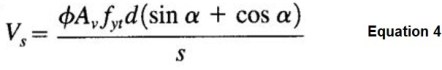
Equation 3 used to compute shear strength of vertical stirrups. If stirrups are inclined, Equation 4 should be used to compute shear strength:

2. Minimum Shear Reinforcement
If Vu, the shear force at factored load, is no larger than (∅Vc), then theoretically no web reinforcement is required. Even in such a case, however, ACI Code required provision of at least a minimum area of web reinforcement equal to:


3. Minimum Spacing between Stirrups
It is undesirable to space vertical stirrups closer than about 100 mm. The size of the stirrups should be chosen to avoid a closer spacing.
4. Maximum Spacing between Stirrups
The maximum spacing between stirrups is smallest of the following provided that (Vs<0.33(fc')0.5bwd):


For longitudinal bars bent at 45 degrees, the second equation above is replaced by Smax=3d/4
In no case, according to ACI Code, is Vs to exceed (0.66√(fc′) bwd) regardless of the amount of web steel used, otherwise, the dimension of the beam needs to be increased.
Procedure for the Shear design of RC Beam
The shear design includes the estimation of stirrup spacing to support ultimate shear. Commonly, part of concrete will resist shear force but the portion of which is not supported by concrete will be carried by shear reinforcement.
- Firstly, compute the ultimate shear force.
- Secondly, estimate design concrete shear strength, use Equation 2 times strength reduction factor.
- No shear reinforcement is needed if Vu< 0.5

- If 0.5
- Provide shear reinforcement when Vu>
- If step 5 is met, compute shear force (Vs) that should be resisted by stirrups, use Equation 1.
- Select trial web-steel area based on standard stirrup sizes ranges from NO.10 to NO.16.
- Multiply shear reinforcement area by a number of stirrup legs to calculate shear reinforcement area.
- Find spacing for the stirrup, use Equation 3 or Equation 4.
- Distribute stirrups uniformly over short span beams.
- However, over long spans, it is more economical to compute the spacing required at several sections. And, place stirrups accordingly in groups of varying spacing.
- The required spacing shall be equal or less than maximum spacing calculated using Equation 6.
- If Vs is greater than 0.33fc’^0.5bwd, then these maximum spacing shall be halved.
- Finally, draw the design beam with longitudinal and shear reinforcement.
Where:


Example
A simply supported rectangular beam 400 mm wide having an effective depth of 550 mm carried a total factored load of 137 KN/m on a 6 m clear span. It is reinforced with 4914 m2 of tensile steel, which continues an interrupted into the supports. Design the beam for shear using vertical U stirrups.
Material properties: fc′=28 MPa , and fyt=420 MPa
Solution:
Compute shear force on the beam by using equation or draw shear diagram:


Shear force at the face of support is 411 KN. However, for simply supported beam, the location of the critical section for shear design is at distance (d), where (d) is effective depth. So, shear force at a critical section of the beam is computed as follow:
Vu, at distance (d)= (411*(3-0.55))/(3)= 335.65 KN
Compute design shear strength of concrete:
![]()
Since Vu, at distance (d)=335.65 KN> ![]()
Vs,required= Vu, at distance (d)-![]()
Vs,required=187.22 KN<0.66*(28)(1/2)*400*550*10-3=288.12 KN, Therefore the dimension of the beam satisfies shear requirements.
Assume stirrup diameter and compute its area:
Assume stirrup NO. 1
Av=(PI/4)*(10)2*2= 157.079 mm2
Compute required spacing between stirrups by using Equation 3:
S=(0.75*157.079*420*550)/(187.22*103)= 145.35 mm, round this value to 140 mm for simply placement work.
The value of (145.35 mm) is greater than minimum spacing which is (100 mm). However, it should not surpass maximum spacing as well.
Determine maximum reinforcement between stirrups using Equation 6:
Smax=((157.079*420)/(0.062*(28)(1/2)*400))=<((157.079*420)/(0.35*400))
Smax=502.73=<471.237
Smax=d/2= 550/2= 275 mm
Smax= 600 mm
The smallest value is 225 mm, therefore
Smax= 275 mm> required spacing which 140 mm
Now, distribute stirrups according to ACI code requirements:
Theoretically, if concrete shear design strength is greater than shear force, then no stirrup is required. However, the ACI code specifies that minimum reinforcement (i.e maximum spacing) should be provided for such area.
The ACI code also stated that, no shear reinforcement is required if shear force is less than half of concrete shear design strength. We will determine these locations and superimposed on the shear diagram of the beam. Half of the beam will be taken into consideration because the beam is symmetry.
From geometry of shear diagram, the distance (x) beyond which stirrups is not required is:
(411/3)=((411-74.213)/x), x=2.458 m
The distance beyond which minimum reinforcement (maximum spacing is needed is:
(411/3)=((411-148.426)/x), x=1.916 m
So, the required spacing (140 mm) should be used within a distance 1.916 m from the face of the support.


The stirrups can be distributed in the following pattern. The first stirrup is placed at (spacing/2) from the face of the support:
1 stirrup at s/2=140/2= 70 mm
13 stirrups at a distance of 140 mm, 13*140= 1820 mm
3 stirrups at a distance of 275 mm, 3*275= 825 mm
Total distance= 70+1820+825= 2715 mm
FAQs
The shear capacity of RC beam is the combination of concrete shear strength and shear strength provided by web reinforcement.
Concrete is weak in carrying shear force.
1. Flexural failure in which cracks are mainly vertical in the middle third of the beam span.
2. Diagonal tension failure, this failure precipitates if the strength of the beam in diagonal tension is lower than its strength in flexure.
3. Shear compression failure in this case the beam has a small shear span/depth ratio of the magnitude of 1-2.5 for concentrated loading and less than 5 for distributed loading.
Shear reinforcement is designed to resist shear forces in excess of the shear strength of concrete. They are provided in forms of vertical or inclined stirrups or longitudinal reinforcement bent up at 45 degrees at locations where they are no longer needed to resist bending.
1. Carries a portion of flexural factored shear force.
2. Restrict the growth of diagonal cracks.
3. Hold the longitudinal reinforcement bars in place.
4. Provide some confinement to the concrete in the compression zone if the stirrups are in form of closed ties.
Read more
Failure modes in reinforced concrete beams: flexural failure and shear failure