

What is Castellated Beam? Why we provide it?

It is generally assumed to be 250 MPa.
It is generally assumed to be 250 MPa.
See lessJoin TheConstructor to ask questions, answer questions, write articles, and connect with other people. When you join you get additional benefits.
Log in to TheConstructor to ask questions, answer people’s questions, write articles & connect with other people. When you join you get additional benefits.
Lost your password? Please enter your email address. You will receive a link and will create a new password via email.
What is Castellated Beam? Why we provide it?
What is the compressive strength of Fe500 rebars?
It is generally assumed to be 250 MPa.
It is generally assumed to be 250 MPa.
See lessWhat is the reinforced concrete deep beam and where it used?
Reinforced concrete deep beam is defined as that members with clear spans in equal or less than four times the overall member depth or regions of beams that are loaded on one face with concentrated loads within twice the member depth from the support and supported on the opposite face so that compreRead more
Reinforced concrete deep beam is defined as that members with clear spans in equal or less than four times the overall member depth or regions of beams that are loaded on one face with concentrated loads within twice the member depth from the support and supported on the opposite face so that compression struts can be developed between the loads and supports.
See lessAt which structure (place) retaining wall resist passive earth pressure?
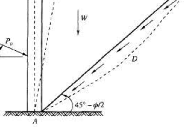
The moment of the wall towards the backfill, in this case, the lateral earth pressure called a passive earth pressure. In the case of passive earth pressure, Major principal stress = lateral pressure Minor principal stress = vertical pressure In this case, soil exerts a pull on a retaining wall wherRead more
The moment of the wall towards the backfill, in this case, the lateral earth pressure called a passive earth pressure.
In the case of passive earth pressure,
Major principal stress = lateral pressure
Minor principal stress = vertical pressure
In this case, soil exerts a pull on a retaining wall where the inner rupture plane called as a failure plane makes at (45- fi/2) angle with horizontal.
At depth=0 , Rankines passive force= 0
If q is a surcharge load acting on backfill, then lateral pressure = K.q applied throughout the depth of retaining wall.
See lessWhat is the procedure to design the double angle tension member in steel structures with formulas? Kindly elaborate on it?
As per Section 6 (Design of Tension Members) of IS 800:2007 – Code of Practice for Construction in Steel, The design strength of the tension member is the minimum of following, Design strength due to yielding of the gross section (Tdg) (Clause 6.2 of IS 800:2007). Design Strength Due to Rupture of CRead more
As per Section 6 (Design of Tension Members) of IS 800:2007 – Code of Practice for Construction in Steel,
The design strength of the tension member is the minimum of following,
Let’s take an example to understand the designing of double angle tension member:
Data Known:
Service Load, T = 200 N/mm2
STEP 1:
Factored Load, Tu = Tdg = 1.5 x 200 = 300 N/mm2
Considering the tension member fails due to yielding of gross section, determine the gross area of angles required.
Tdg = AgFy/ꙋm0 → Ag = Tdgꙋm0/Fy
Ag = (300 x 103 x 1.1)/250 = 1320 mm2
The total gross area of tension member (Ag) required is 1320 mm2. Remember this is the area of two angle sections. Therefore,
Gross area of single angle section (Ag1) = (Ag)/2 = 1320/2 = 660 mm2
From steel table (SP 6-1), choose an angle having gross area of single angle about 25% to 40% more than computed above.
Taking Rolled Steel Equal Angle ISA 60x60x8 having following properties,
Sectional Area, A= 896mm2
Total Gross Area, Ag0 = 2×896 = 1792 mm2 > 1320 mm2 (O.K)
STEP 2:
Designing Connections: – We can provide either bolted or welded connections, so let us provide bolted connections.
Total thickness of angles having outstanding legs placed back to back,
ta = 8+8 =16mm
Let us provide 20mm diameter bolts of grade 4.6 and Steel of grade Fe415,
Diameter of bolt, d = 20mm
Diameter of bolt hole, dh = 20 + 2 = 22mm (Table 19 of IS 800:2007)
Fu = 410 N/mm2
Fub = 400 N/mm2
Fy = 250 N/mm2
Kb = 0.606
= 2 x (Fub/√3) x (Anb/ꙋmb) where, Anb = 0.78 x (πd2/4)
= 2 x (400/√3) x ((0.78 x (π(20)2/4))/1.25)
= 90.545 KN
= (2.5 Kb d t Fub)/ ꙋmb
= (2.5 x 0.606 x 20 x 16 x 400)/1.25
= 155.136 KN
Therefore, Bolt Value = Least of (90.545, 155.136) = 90.545 KN
No. of bolts required, N = (Tu/Bolt Value) = (300/90.545) = 3.31 ≈ 4 nos
STEP 3:
Check of Strength due to rupture of critical section,
The design strength,
Tdn = 0.9Ancfu/ꙋm1 + βAgofy/ ꙋm0
Where,
β = 1.4 – 0.076(w/t)( fy/fu)( bs/Lc) ≤ (fu ꙋm0/fy ꙋm1)
≥ 0.7
w = outstand leg width = 60mm
t = total thickness of angles = 16mm
w1 = end distance = 40mm
bs = shear lag distance = w + w1 – t = 60 + 40 – 16 = 84mm
Lc = length of end connection = 3 x 60 = 180mm
β = 1.4 – 0.076(60/16)(250/410)(84/180)
= 1.4 – 0.081
= 1.319 ≤ (410×1.1/250×1.25) = 1.4432 (OK)
≥ (0.7) (OK)
Anc = (60+60-2 x 22) x 8 = 608mm2
Ago = (60 x 16) = 960mm2
Tdn = 0.9Ancfu/ꙋm1 + βAgofy/ ꙋm0
= ((0.9 x 608 x 410)/1.25) + ((1.319 x 960 x 250)/1.1)
= 179481.6 + 287781.81
= 467343.6 N
= 467.34 KN > 300 KN (O.K)
STEP 4:
Check for Strength Due to Block Shear (Tdb),
Tdb = [(Avgfy)/(√3ꙋm0) + (0.9Atnfu)/( ꙋm1)] or [(0.9Avnfu)/(√3ꙋm1) + (Atgfy)/(ꙋm0)]
Avg = 220 x 16 = 3520 mm2
Avn = (220-3×22-(22/2)) x 16 = 2288 mm2
Atg = 40 x 16 = 640 mm2
Atn = (40-(22/2)) x 16 = 464 mm2
Tdb = [((3520×250)/ (√3x1.1)) + ((0.9x464x410/1.25)]
= 461880.22 + 136972.8
= 598853.02 N
= 598.85 KN
Tdb = [((0.9x2288x410)/ (√3x1.25)) + ((640×250/1.1)]
= 389952.53 + 145454.54
= 535407.07 N
= 535.41 KN
Tdb = min (535.41, 598.85) = 535.41 KN > 300 KN (O.K)
Therefore, the selected section is safe.
So, Provide 2 ISA 60x60x8 angles placed in such a way that outstanding legs are placed back to back and attached with 20mm diameter bolts of grade 4.6. Edge distance and End distance is 40mm and pitch is 60mm.
See lessWhy we provide Anchor Bar in a single RC beam?
Anchor bars are the bars which are given on compression side to hold the stirrups or lateral reinforcements and the main bars.
Anchor bars are the bars which are given on compression side to hold the stirrups or lateral reinforcements and the main bars.
See lessWhat is use of ILD diagram at site?
ILD or Influence Line Diagram shows us the effect of a point load at some point on a structural member with respect to the position of the load. So, ILD tells us what and where would be the maximum effect of a load places at what location. So to visualize the worst-case scenario and best-case scenarRead more
ILD or Influence Line Diagram shows us the effect of a point load at some point on a structural member with respect to the position of the load.
So, ILD tells us what and where would be the maximum effect of a load places at what location. So to visualize the worst-case scenario and best-case scenario and the variations I between, ILD is a comprehensive aid.
The most common usage is in Bridges, rail tracks, and roads where loads are always pointed loads (axle loads) and always moving. Knowing when and how much will be the maximum effect like bending moment, shear force, etc. helps us set up the design values.
See lessHow to calculate stiffness of storey to avoid soft storey of multi-storeyed building?
Avoid soft storey? A soft storey is a storey with lateral stiffness less than the storey just above. So technically, you cannot avoid soft storey just by calculation. Right? Well, according to the new code for seismic design, IS 1893 Part I (2016), infill masonry walls in soft storeys of RC buildingRead more
Avoid soft storey? A soft storey is a storey with lateral stiffness less than the storey just above. So technically, you cannot avoid soft storey just by calculation. Right?
Well, according to the new code for seismic design, IS 1893 Part I (2016), infill masonry walls in soft storeys of RC buildings can be modeled as diagonal struts to contribute to lateral stiffness.Though this doesn’t guarantee that the resulting storey stiffness with the contribution of infill walls, will be greater than that of the storey above.
Method :
[Note : Even after reading the answer please do refer to table 6, fig. 4 and section 7.9 of IS 1893 Part I (2016) for two formulae mentioned above and a clearer understanding of the method in detail.]
See less


Vivek Patel
The castellated beam is a modified steel beam. In which the beam is cut in the central web portion were no great force is present. Cut near to neutral axis of the beam where we required less amount of material mass to resist various force. The opening shape may be hexagonal, rectangular, circular, eRead more
The castellated beam is a modified steel beam. In which the beam is cut in the central web portion were no great force is present.
Cut near to neutral axis of the beam where we required less amount of material mass to resist various force.
The opening shape may be hexagonal, rectangular, circular, etc.
Due to opening in web we get some benifit
- Saving in material
- Lighter weight
- Due to increased depth allowed, we get more strengthen beam
- Good aesthetic view
- Esay handle with roof febrication work.
See less